
System Characteristics
This section describes, in brief, the purpose of each section of the Tie-FenLock 400 system
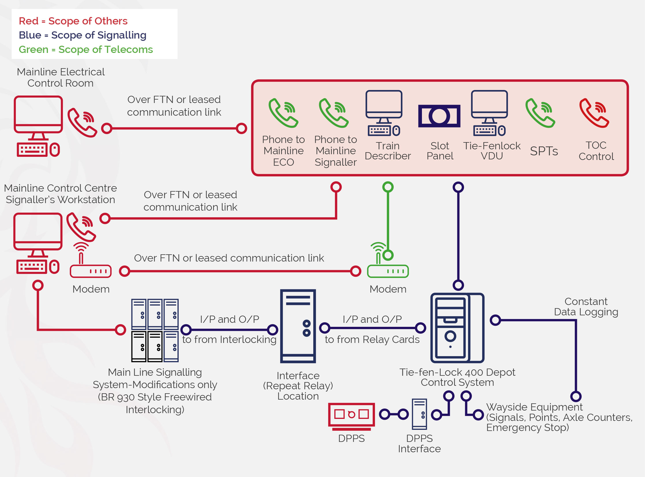 Figure 2 – System block diagram of a typical Tie-FenLock 400 depot installation
The main function of the Depot Control System is to provide a signalling interlocking. The interlocking is designed to prevent conflicting train movements and to provide a safe state in the event of a failure. The VDU is the human-machine interface (HMI) from which the operator can make interlocking requests. This request (route setting etc.) will go through the interlocking, which analyses the status of the wayside equipment (track sections, point machines, other set routes etc.) and approves/rejects the request. If the request is approved, the route state and wayside equipment state changes to allow one train movement.
The philosophy of a centralised control is achieved by providing all controls available to the operator within one location. Using Figure 2 as a typical installation, the “Depot Signaller’s Control Desk” is the location of all signalling and communications devices available to the operator. This includes all signalling controls, CCTV controls and screens, telephones to SPTs/TOCs/mainline entities (as required) and any degraded operation controls (such as point keys and handles).
The mainline functional interface is becoming a more prevalent feature of depot designs following the introduction of the following documents:
It has now been stated that train movements are to be less reliant on voice communications and these should be avoided. Where a mainline interface is proposed a safe method of working shall be established. This can be achieved by creating specific routes to/from the mainline, controlling these routes using the mainline control system and a slotting arrangement under control of the depot operator.
The Tie-FenLock system also provides provision for a train describer for interposed headcodes to be transmitted to the mainline train describer system.
The DPPS interface allows safe movements of trains into and out of areas where there is a risk of injury from train-human interaction due to increased human activity in a depot area or collision with track mounted equipment, such as in a maintenance shed or wheel lathe. A slotting arrangement, controlled by the DPPS operator, can allow or block movements into or out of the area dependent on the conditions within the DPPS area. This interface can be made to work automatically in the event that no staff are present.
The Tie-FenLock system is highly scalable. It is capable of providing control and indication for depots of significant complexity. This is due to the modular interlocking and wayside architecture enabling the overall system to be separated into multiple substations. Logical division of the interlocking is recommended for installations with over 60 items of signalling equipment. Equipment counts higher than this are possible but, depending upon the depot layout, this could be to the detriment of system processing speed.
The largest Tie-FenLock installation is located at Gdansk depot, Poland. The depot consists of 4 substations which control 100 point machines, 180 axle counter heads and 150 signals. Each of these substations communicates (bi-directionally) with the main interlocking processor.
All Tie-FenLock systems are compatible with relevant EU EMC standards to all traction types. Outdoor equipment has a temperature operating window of at least -25°C to +45°C. The axle counters can be safely traversed at speeds of up to 60kph (~37mph) although a typical depot speed limit is usually less than 15mph.
System Architecture
Computer Based Interlocking
This is the “heart and brain” of the Tie-FenLock 400 system. The Central Control Unit (CCU) is a SIL-2 system and is battery buffered by an uninterruptable power supply (UPS) to prevent power loss. In the event of a total power loss/UPS failure the internal memory is not lost. The CCU collects and distributes data to all wayside equipment and feeds the information to the Central Processing Unit (CPU). The CPU contains the interlocking data, which is bespoke to each installation. The interlocking data can be written to adapt to and abide by any country’s signalling principles with no limitations which may include permissive working or long route setting (non-exhaustive).
The operator’s VDU is connected to the CPU, which takes the operator’s inputs on the VDU and checks against the CCU interlocking data before granting or blocking the action requested by the operator.
All equipment is fed from and reports to an “interface card” which is mounted within the location cabinet/REB (see section 4.2.2). Each card communicates with other cards and the CCU.
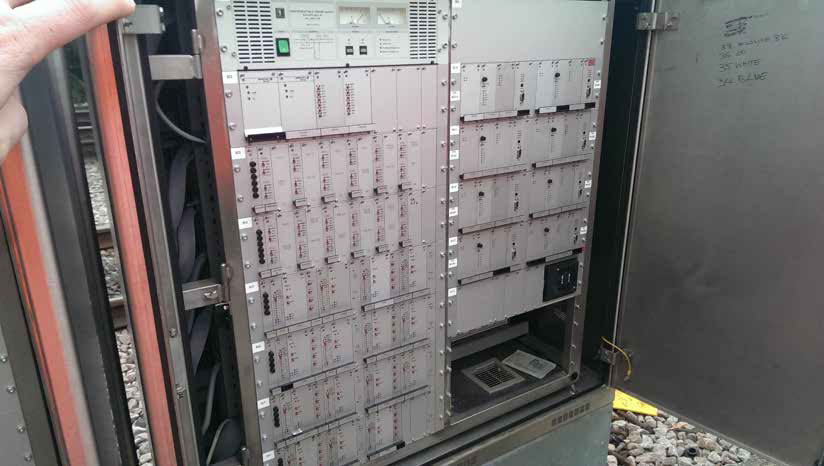 Figure 3 – Interlocking cards (Wembley Depot, UK)
The CCU is largely maintenance free, with no scheduled upgrades unless required by depot expansion. The system performs self-diagnostic routines which flags untoward occurrences and failures. Upgrades to the software can be implemented by installing a new CPU, which allows for easy installation of new roads, signals and points etc.
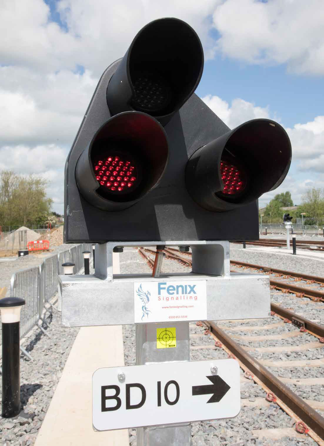
The system boasts a modular design philosophy which is created from high grade industrial components, thus increasing the availability of spare parts and reducing maintenance costs. The system is constantly performing self-checks on the circuits and reporting faults, which means that malfunctioning units can be swapped very quickly and easily. The metal plates on the front (see figure 1) can be taken off, exposing the card beneath. This card has a part number and pin-code, meaning only a card of that type can replace the original.
Equipment Housing
Overview
The Tie-FenLock 400 system is installed in location cabinets, preferably in internal housing such as a control room or REB for ease of maintenance but can also be externally located. Unlike typical NR location cabinets, these are mounted on a swinging frame and therefore provides access from one side. The frame is made up of two columns of eight 19” racks (although typically only a maximum of 7 are used to allow cable installation and access in the base of the location), on which the cards to control and process wayside information is mounted, as well as the CCU and CPU.
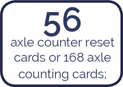
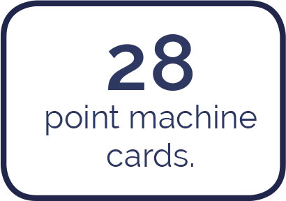
Each location cabinet can hold a maximum of:


An additional external cabinet can be provided for terminating and distributing the incoming power supply. This cabinet is smaller than the cabinets depicted in Figures 3 and 4. The UPS can also be located for electrical convenience within this cabinet. The UPS is typically specified for axle counting back-up purposes and not for signal and points power, but it can be specified for any purpose, voltage or time period to suit specific project requirements.
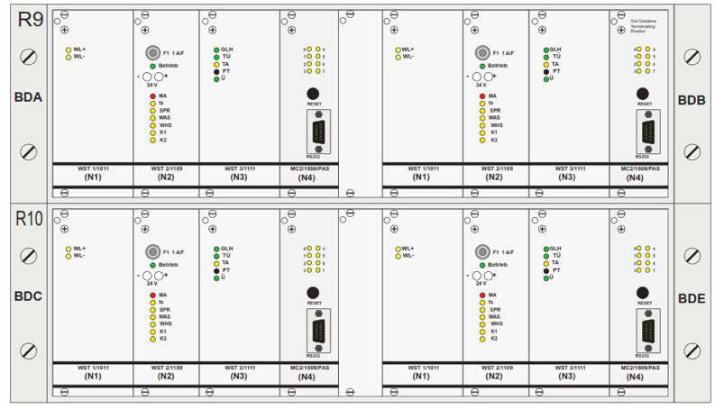 Figure 4 – Design drawing of two 19” racks, controlling 4 point machines
External
The external cabinets are mounted on a stainless-steel base, which is directly buried into the ground. The base allows for cable entry and exit and features removable panels to allow access for maintenance and to provide protection to the cables entering the base of the cabinet. Cables are attached directly to the bottom of the cabinet by suitably rated cable glands and armour can be earthed.
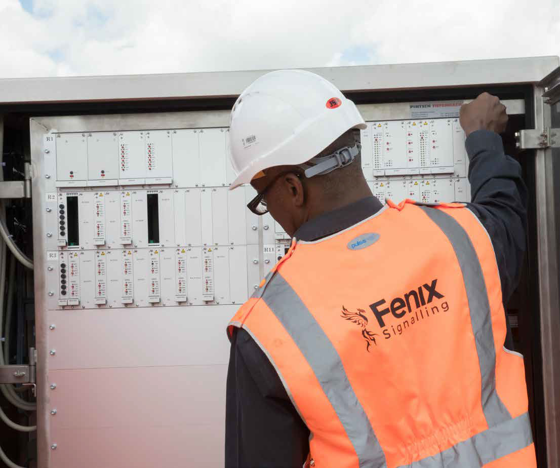 Figure 5 – External location cabinet (frame closed)
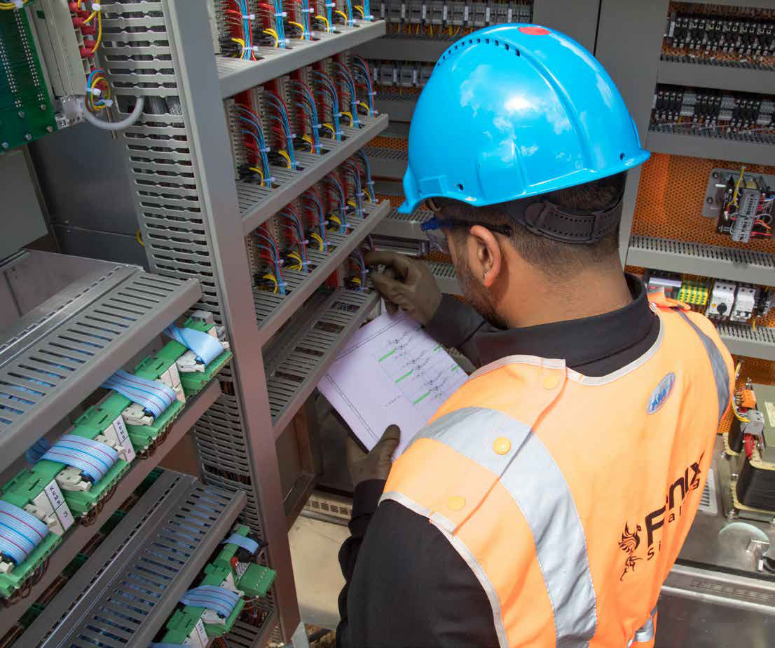 Figure 6 – External location cabinet (frame open)
The racks and frames are also compatible with indoor application, where a glass fronted cabinet can be mounted to the floor or wall within a designated building, or within a relocatable equipment building (REB). This is beneficial as a centralised system offers easier maintenance (access to all of the system in one location, protected from weather, reduced cost of exterior cabinets, concrete bases etc.)
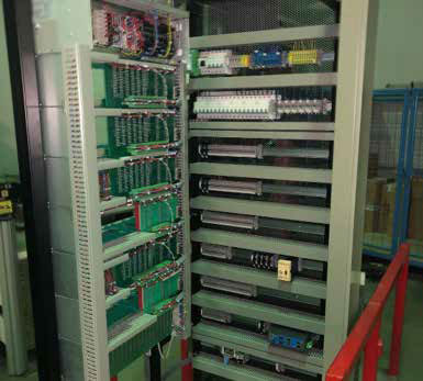 Figure 7 – Wall mounted internal location cabinet (undergoing factory testing)
VDU
The purpose of the VDU is to be the HMI to the depot controller enabling safe control of train movements with indication of track and wayside system status. The information displayed and colours on the VDU can be customised to the client’s requirements, although typically the colours are to NR standards.
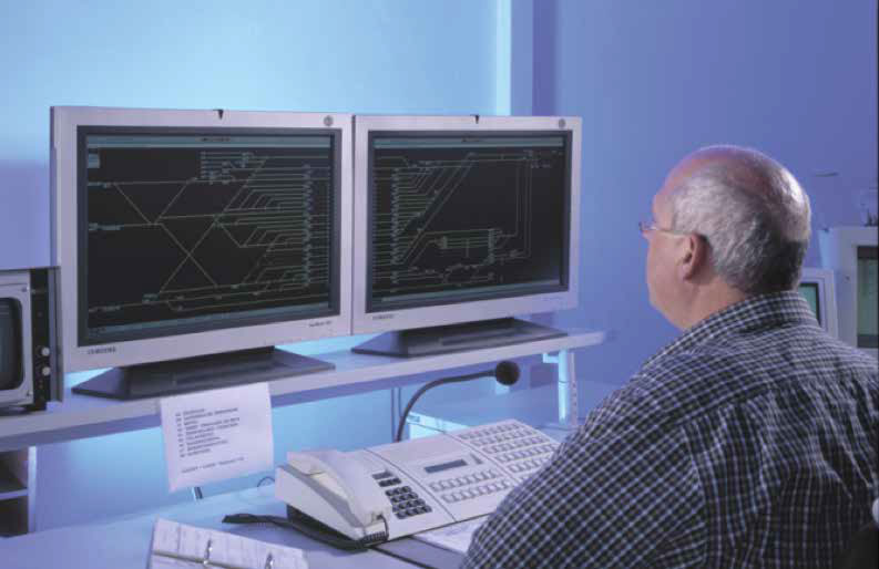 Figure 8 – VDU at Cologne Depot, Germany
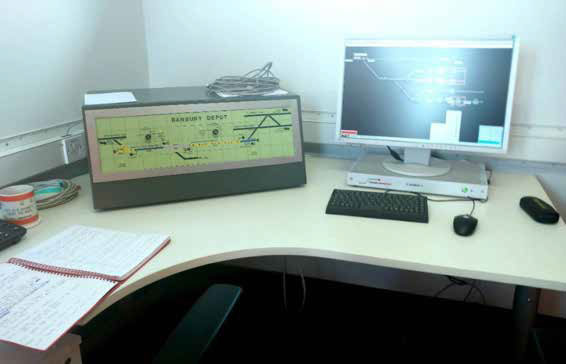 Figure 9 – VDU at Banbury Depot, UK (NR slot panel to left)
Depending on the size of the depot, one or multiple LCD (being SD or HD) monitors are provided along with a compact desktop computer, mouse and keyboard. All other signalling and telecommunications equipment (e.g. slot panel, train describer, emergency alarms and telephones) should be mounted locally to the VDU, in order to achieve centralised control for all movements.
Axle Counters
The axle counter for the Tie-FenLock 400 is a SIL-4 system which informs the operator of track occupancy and provides vital interlocking functions. A SIL-2 version is also available for when SIL-4 is not required.
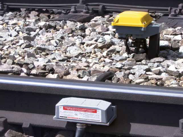 Figure 11 – Axle counter mounted on rail, and disbox (background)
The axle counter head is a dual proximity switch, designed and manufactured to detect the flange of the wheels passing over the switches. With each detected wheel, the axle counter counting card sends a package of data to the switching amplifier, which is within the location cabinet.
The cable connecting the axle counter to the disconnection box is a fixed tail cable, of varying lengths depending on specification. The cable from the location case to the disconnection box is usually a 2-pair telecoms-style cable, however if two axle counter heads are mounted close to each other, it is possible for the two heads to share a 4-pair (up to 5-pair) cable, as the axle counter head disconnection box allows this.
The axle counter heads require little maintenance; a biannual visual inspection for damage and clearance to the height below the railhead, an annual test and, if necessary, adjustment of the detection mechanism.
The axle counters can be located at a maximum of 2200m when using a 1.4mm2 cable under harsh EMC environments, or up to 8,600m when using a 1.4mm2 when using an earthed shielded cable.
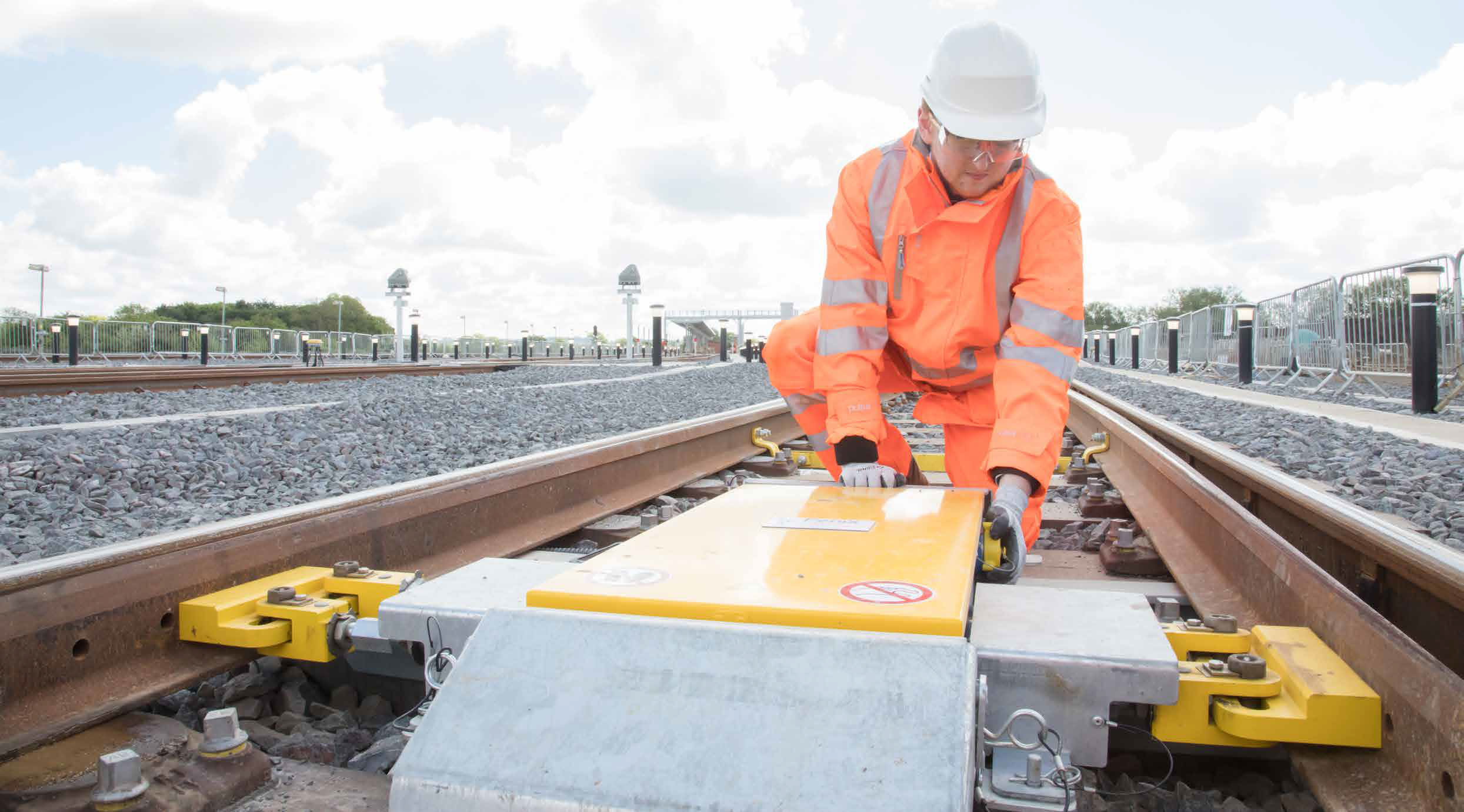
Point Machine
The Tie-FenLock 400 system uses low-maintenance trailable point machines which are robust and mounted in the four foot. The machine can be installed in approximately 80 minutes and tested and commissioned in under two hours, saving considerable time and cost on site compared to rival machines. It is mounted on two cross members which clamp to the outside foot of the rail and the overall height of the machine is below the standard BS113 rail running height. A six-foot mounted version is also available, depending on client requirements/site layout restrictions.
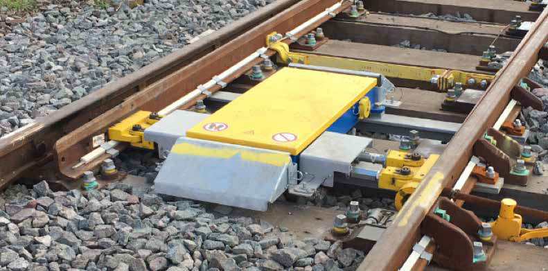 Figure 12 – Point machine installation
The detection and power are supplied by a single cable, with a minimum of 5 cores. The power supply is currently a three-phase 400Vac supply, although a 120Vdc variant is in development. The maximum cable feed length is 1000m when using a 1.4mm2 cable, or 500m when using a 0.9mm2 cable.
The points machine features an internal mechanism allowing the machine to be safely used in a trailing direction without damaging the components. The machine can be installed with a plate which allows the integration of a standard six-foot mounted back drive. In the event of a power failure, the machine can be operated manually by inserting a key to engage manual operation and then turning a crank handle. Various throw lengths and times can be specified and supplied.
The machine requires minimal maintenance at an interval of every 6 months, which is limited to the exterior of the machine. This is normally to account for vibration and wear in the turnout. It includes adjustment of the detection rods and maintenance of the screw thread to prevent rusting, in addition to re-torquing the bolts.
When an over-running and/or a trailing move is detected, if safe and in combination with the axle counter system, the points automatically throw the points to the non-trailing position to prevent damage to the infrastructure/train.
The machine is driven by an electric motor which is geared down to drive the switch blades by two rods. The rods feature a spring mechanism to prevent breaking when the machine is trailed. The detection is achieved by four micro switches attached to two detection rods.
System Interfaces
Interfaces to Other Equipment
Relay cards are available to install within the card racks, allowing almost any technology to be interfaced to the interlocking. This may include:


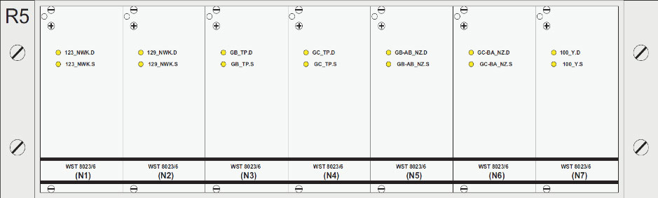 Figure 13 – Relay card rack for interface functions
Each relay card has two sets of two antivalent contacts (one set normally open, one set normally closed) meaning that double cutting contacts into the circuits can be achieved. For outgoing circuits to Network Rail location cases, a BR-spec transformer is used to provide earth-free power.
Should a different type of point operating equipment to section 4.2.6 be specified, the relay cards can be used to gather detection information from the points operating equipment.
Mainline Interlocking
The Tie-FenLock 400 system can be interfaced to any type of interlocking (such as but not exhaustive: electro-mechanical, relay, SSI or CBI) by implementing an interface with BR930-style relays. The relays can be housed in a separate interface location case amongst the mainline suite, within the depot suite or within the depot signalling equipment room. This arrangement creates a volts-free contact bridge, meaning the systems can operate independently from each other and maintain immunity. An interface functional specification shall be written beforehand to ensure all relevant functions are sent and received from each interlocking. Typically, a slot arrangement is required to ensure a systematic and operator handshake is achieved.
Emergency alarm systems can be integrated into the Tie-FenLock 400 VDU and interface. The system also features an emergency all signals on control button on the VDU.
Typically, a train describer does not interface with the Tie-FenLock 400 system as it is more efficient for the fringe signal box to perform this action, or the user to interpose headcodes into a separate TD monitor.
Depot Personnel Protection System (DPPS)
Typically, a slot or other equivalent acknowledgement is required from the DPPS designated person prior to a train movement. This slot is sent to the Tie-FenLock 400 system and integrated in the controls of the appropriate signal. The DPPS shall send a movement authority slot when it is safe for a train to move into a DPPS area, allowing the route setting and aspect clearance. If it is not given, the route cannot be set.
Points Heating
A centralised points heating system can be integrated into the depot signalling system to show faults, warnings and system operation on the user’s VDU. The system can also be turned on and off using the buttons on the VDU.
Cable Routing
It is recommended to run two separate or segregated troughing routes, one for the point machine cables and signal cables, the other for axle counter and other data cables. This removes the chance
of interference between the cables. If this cannot be achieved it is satisfactory if a 50mm air gap is maintained between the two cable sets.
Typically, copper cable cores are used. However, for cables used for data purposes (from the interlocking to the VDU, axle counters etc.) a fibre-optic cable can be specified.
In areas with harsh EMC environments, earthed cable sheathing may be required for long cable runs to maintain compliance and to mitigate voltage induction.
Power Supply
The Tie-FenLock 400 requires a 3-phase 400Vac supply to a separate power cabinet or enclosure where it is transformed down and/or distributed as required. The interlocking components predominantly run off 12V and 24V, with the exception of the signals (110Vac) and point machines (400Vac).
A 30 minute back up power supply is generally provided for the axle counter logic computer, to allow for axle count and train position memory, allowing a quicker recovery time/reducing downtime.
Forward House
High Street
Henley in Arden
B95 5AA
T: 03300 580180
T: 01926 358428
Click here to subscribe to updates from Fenix Rail Systems